Monday, December 17, 2018

Idle Advanced Settings

Hey, long time no post :|

I'm starting my second year studying Electronics Engineering  - no time for nothing...

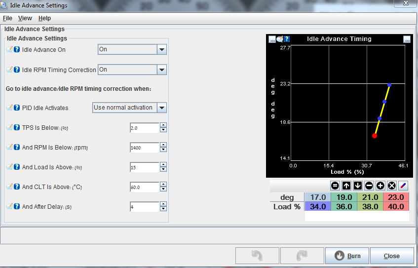
The last piece in the idle puzzle is the "Idle Advanced Settings".

Lets talk about it a little first.
In order to help stabilize idle rpm we can use this mechanism too, meaning we play around with timing at idle in order to help too low or too high rpm - we can do that in a very good resolution resulting very stable idle.

BTW, if you ever checked via OBD the timing angle on a stock car you would see that the idle timing is playing around - keeping the idle steady.

Less timing = less RPM
More timing = more RPM

What we want to tune:
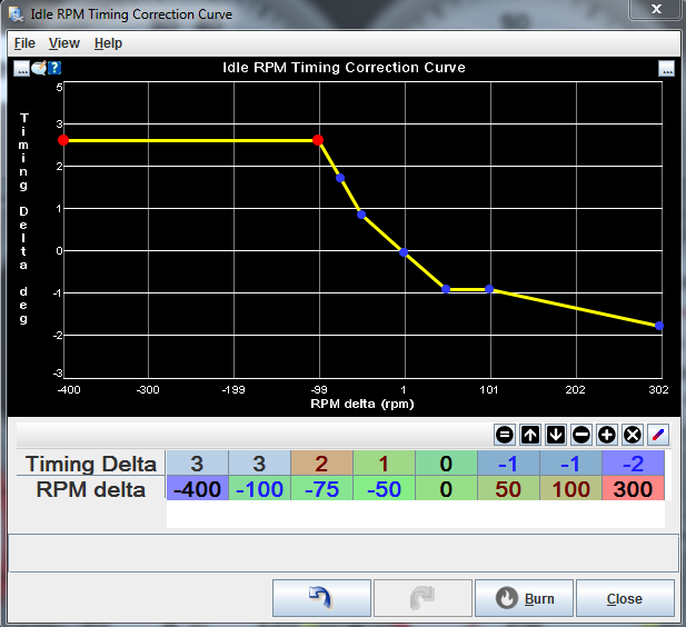
MORE timing @ lower then desired idle rpm - so the rpm will rise a little.
LESS timing @ higher then desired idle rpm - so the rpm will lower a little.

Got it ?

You can play around with big numbers and low numbers - both for the delta (the rpm change) and for the timing value.

The Settings:

"Idle Advanced On" : Idle advanced reacting to load change.
"Idle RPM Timing Correction" : Idle advanced reacting to RPM offset from desired idle rpm.

The rest is the conditions to meet in order to start "Idle RPM Timing Correction" or "Idle Advanced On"


Values for "Idle RPM Timing Correction":


You can try different resolutions for the rpm delta and the timing delta.

You hope it helps !

Have fun.

Sunday, October 22, 2017

How to control VCT (VVT) using DIYPNP

VVT (VCT) Control using DIYPNP ?? No way ! well yes :) Just keep reading

Any one who considered a VVT (BP6D) engine swap had to answer the VVT question (Mazda calls it VCT), How I'll control it ? New ECU ? VVT Tuner ? Leave it disabled ?

Well, you can go either way but if you have a DIYPNP installed already you can use it to control VVT.

You need to wire the VVT solenoid to the ECU location, on the board you need to use ALED or WLED outputs, wire the output you choose to the external pins.

You need to supply 12v and GND(ALED/WLED) in order to control VVT.

After all is wired we want to configure it.

One little explanation before we actually do, "Real" VVT control consist of a 3D table the utilize LOAD, RPM and duty cycle.

Like so : (Taken from MS3 Basic)


The idea is to apply smooth transit in and out of full VVT camshaft advance.
On the DIYPNP we do not have this kind of table/control BUT we can enjoy the VVT nonetheless !
Our control will consist of a on/off trigger.

My VVT tests on the dyno show a performance gain from very low rpm (<2000) upto 5500~.
For the best tune you need to enable VVT at around 2000rpm and disable it at 5500~, in order to do that we configure the WLED/ALED output as follow:


Just keep the "On" trigger away from your stop and go speed.

Very noticeable improvement ! Enjoy !


Sunday, September 24, 2017

Flatshift and Launch control - 2 step

Always wanted to shoot flames and make gun shots sounds from your tail pipe ? GOOD !

Let me show you how.

I will guide through how to setup launch control and how to setup flat shift, lets go.

Launch control will hold your RPM at launch rpm even when standing in WOT.
You will need to try and see what is the best config for your setup.

Requirements:

  • Clutch switch (sensor) must be connected to an input on the ecu, on my DIYPNP I wired it to FLEX input.
  • No catalytic converter (for flames and bangs)

Wiring:

1L (on 97)
1V (on 95)
 = Clutch switch

1L/1V to Input2In
Input2Out to FLEX

TunerStudio setup:


Here you can choose if you want to enable Launch only or Launch+Flatshift (or turn it off)
You'll need to config the input pin - FLEX in my case.
The next 5 rows are the Launch control configuration, 
At what rpm to hold for launch.
Soft limit mean at what rpm it will start acting  - it is like a transition stage.
Retard is the BOOM config.... how many deg to retard when activated - test to see what BOOM you like best...
TPS % is activation condition must be > 0%.
Limiter method: for BOOMs choose "Spark Cut" the other will limit you but in a more civilized meaner.

The last 3 lines config FS(flatshift).
FS will hold your rpm at high rpm (not red line revlimiter) in order to shift gears when in WOT.
Usually the rpm should be around 5000-5500, it will allow the best FS, of-course you should try and see what is best for you.

Forced induction engine benefit the most form FS, it will allow gear changing with very little boost lost.

Arming: FS start
Hard: FS limiter
Retard: deg to retard

After it is all ready and working, play around with the numbers and find the best set up for you.

Final tip: Install an On\Off switch on the clutch switch line in order to be able to turn off this party when not needed - trust me you want that.

Have fun !!


Monday, December 26, 2016

Barometric correction for 12$

Hey,

Barometric correction will help your fueling when going dramatically below/above sea level.

Hardware needed:

Hope it is still on.


It is the same sensor as the DIYPNP MAP sensor. (now you will have two of them :))

Installation:


Mount the second sensor on top of the first, solder the legs together as shown in the picture, solder the left most leg to the baro hole on the PCB.

k ?

Setup:


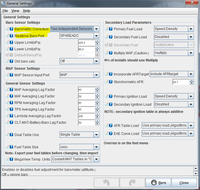
Change this two as shown in the picture.

Tune:


This is untuned of curse, the reason is that I use the EGO correction and I  usually drive at sea level...

You can tune the curve to add or decrease fuel according to barometric pressure.

Have fun :)


Sunday, July 31, 2016

Closed Loop Idle REV 2.2

Closed Loop Idle REV 2.2

Overview
CLI is intended to help keep steady idle when the load on the engine change, load change can come from: AC compressor,  power steering, fans, lights and electric load in general.
High or low CLT and MAT can change the idle behavior too.

CLI control the idle valve which is an air valve that bypass the throttle.

After some time you run open-loop (PWM-Warmup) and all is good, meaning the idle valve is operational and you can get a relatively good idle and AFR, it is time to try CLI.

Let's dive in, put your swimsuit on.

Closed Loop Idle 

CLI is dynamic air correction mechanism using PWM-idle air valve.

PWM-idle air valve allow air in the engine when the throttle is closed (when the gas paddle is lifted).

CLI will automatically control the PWM-idle air valve in order to sustain steady idle.

Change "Algorithm" to "Closed-loop"


Main CLI menu:


CLI behevuier is consisted of CLI and OLI(open loop idle) operation, when CLI Activation Settings are not met, the ECU will follow OLI settings.
"Closed-Loop Idle Valve Settings" are OLI when CLI Activation Settings are not met.

So, in "Closed Loop Idle" settings, you define IAC(idle air control valve) behavior when in open-loop (PID disabled) and for closed-loop (PID enabled).

The other three PID menus define the delay, behavior and activation values for PID operation.
We start at the first sub menu:

Closed Loop Idle Valve setting:
Idle Valve Close Duty(%): Remember "Output Test mode - Idle Valve" ? put the value you've found, here.
(max closed %)
Idle Valve Open Duty(%): same as above (max opened %)
Dahspot Adder(%): The amount of valve % to add when throttle is lifted. (getting ready for idle rpm)
Dahspot Decay Factor(sec?): How long will it take the adder above to decline to 0 - leaving CLI to follow regular CLITR (Closed Loop Idle Target RPM)
Use Last Value Or Table: "Use initial value table" the other option "use last value" did not work good for me.
Use CLT Or MAT In Table Lookup: I use MAT
Close Delay(s): How long will it take the valve to close when throttle is pressed.
Shift Settings
This settings help the ECU tell when you are just shifting gears or not.
Shifting gears means the ECU does not need to start preparing to idle the engine.
If the situation is not shifting gears then the ECU needs to start preparing to idle the engine.
When you press the clutch, not in order to shift gears, that is when the ECU needs to prepare for idle, meaning, set the IAC at a preset % in order to "catch" the falling RPM.
K ?
Leave Valve Closed Above(rpm): Here you to tell the ECU above what RPM the IAC stay closed, if you change gears then there is no need for the IAC to open.
For This Number Of Seconds(s): This will tell the ECU what is the max time to consider "shifting gears", if throttle pedal is lifted for more then the time set, consider the situation "not shifting gears" - prepare to idle - get ready to catch the falling (fast) RPM - set the IAC at the preset % from "Closed-Loop Idle Initial Values" table.


Next sub-menu:

Closed-Loop Idle PID Delays And Behavior
PID Delay(s): tool tip
Crank To Run Taper(s): How long to keep following  "Idle Cranking Duty/Steps" curve after engine start
PID Ramp To Target Time(s):  tool tip
PID Control Interval(ms): tool tip
PID Disable RPMdot: tool tip

Closed-Loop Idle PID Activation Settings
Idle Activation TPS Threshold(%): highest TPS that allow PID activation.
RPMdot Thershold(rpm/sec): RPM change speed, how fast the rpm change, close to idle or in idle it will be slow (30rpm/sec is slow)
Max Decel Load(%): Lowest MAP that allow PID activation, should be a little below idle MAP.
PID Lockout On Switch Active: If clutch switch is present you can use it here as CLI activator.
PID RPM Window Size (1=Off): tool tip(?)

Closed Loop Idle PID Gains
tool tips

Settings and settings...., let's talk about the whole CLI concept and what happens when.

When I was tuned to run PWM-Warmup (open-loop idle) I had the IAC set to a specific (low) value for idle.

Goods:
- Easy to set up
- Works (sometimes)

Bads:
- Not dynamic - when load at idle is represented to the system the idle rpm will drop and may even stall, same with low\high CLT and MAT it would not "care", it would just do the same (same IAC %) leading to oscillation, too low or too high idle.
- When the throttle is lifted and the clutch is pressed, the rpm run down pretty fast, the static IAC % will not be enough to "hold" and "stop" the rpm from taking a deep dive below desired idle...


CLI - what happen when.
The first trigger that will make MS look into this menu and check what to do is: throttle lift.
When you lift your feet from the throttle, MS is checking to see if you are just changing gears  (Shift Settings: For This Number Of Seconds(s) value) or not  (Shift Settings: For This Number Of Seconds(s) value) and  what IAC % to use in order to give the rpm a "soft" landing just before (Closed-Loop Idle Initial Values+Dashpot Adder) idle (PID idle).

Ok ?

MS will find the answer in "Closed-Loop Idle Initial Values" - meaning, what IAC % @ what MAT/RPM.
I will address this table in a sec.

MS checks the MAT and then looks at CLITR (Closed-Loop Target RPM) to know what IAC % to use.

So, now the IAC is standing by opened, rpm is decreasing, MS checks for  Closed-Loop Idle PID Activation Settings, TPS is good, RPMdot will be good when the rpm will get close to idle range and Max decel Load will be here when the rpm has "landed" and  the engine is close to normal idle MAP (around 30kpa).

NOW ! PID takes control of the rpm following Closed Loop Idle PID Gains as behavior guidelines.

k ?

1. Throttle lifted
2. Not changing gears.
3. Set IAC % for RPM soft "landing"
4. RPM "landed"
5. PID conditions are met
6. PID controls idle
7. Throttle pressed
8. PID disabled
9. IAC closed

Good ? more details ? k !

1. TPS < 1%
2. "Shift Settings: For This Number Of Seconds:(s)" > value
3. IAC % = "Closed-Loop Idle Initial Values" table + Dashpot Adder.
4. Dashpot Decay Factor
5. PID conditions are met
6, PID controls idle
7. Throttle pressed
8. PID disabled
9. IAC closed


Closed-Loop Idle Initial Values:
You can start tuning this table by finding the IAC % / RPM correlation @ a specific MAT.

Run "Output Test Mode - Idle Valve" and find what IAC % will give you what RPM, at what MAT.


Lets say your MAT is 45C and you've found that 37% will set you @ 950RPM, write it down.

Now find what IAC % for 850,900,1000,1200, if the MAT changes, write down @ what MAT what IAC % for what specific RPM.

You should find something like that (for NA):
MAT @ 45C

850RPM @ 33%
900RPM @ 35%
950RPM @ 37%
1000RPM @ 40%
1200RPM @ 54%

Now put it all in the table and add one or two % across the board.


Now your 45C row is correct, higher MAT will need more % and lower MAT will need less %.

This is a very good start, drive around with this table and after a while you will notice the % change you need to make for higher/lower MAT.

Have fun :)


MegaLog Viewer - MLV
If you want to check CLI status in MLV - if MS is in CLI or not, you can choose "status2", when it is 0 CLI is off, when it is 128 CLI is on.


When status2=128 it means that PID is enabled ! 
The whole IAC % landing the rpm is happening before that (every time you lift your feet from the throttle), so you can see in the log that the IAC% is up and status2=0 this is because PID is not active yet, but the IAC % is ready for the rpm...

k ?

Tuner studio
You can add a CLI indicator to TS - just remember it is just the PID activation indicator !


Monday, July 4, 2016

Closed Loop Idle REV 2.1

Closed Loop Idle REV 2.1

Overview
CLI is intended to help keep steady idle when the load on the engine change, load change can come from: AC compressor,  power steering, fans, lights and electric load in general.
High or low CLT and MAT can change the idle behavior too.

CLI control the idle valve which is an air valve that bypass the throttle.

After some time you run open-loop (PWM-Warmup) and all is good, meaning the idle valve is operational and you can get a relatively good idle and AFR, it is time to try CLI.

Let's dive in, put your swimsuit on.

Closed Loop Idle 

CLI is dynamic air correction mechanism using PWM-idle air valve.

PWM-idle air valve allow air in the engine when the throttle is closed (when the gas paddle is lifted).

CLI will automatically control the PWM-idle air valve in order to sustain steady idle.

Change "Algorithm" to "Closed-loop"


Main CLI menu:


CLI behevuier is consisted of CLI and OLI(open loop idle) operation, when CLI Activation Settings are not met, the ECU will follow OLI settings.
"Closed-Loop Idle Valve Settings" are OLI when CLI Activation Settings are not met.

So, in "Closed Loop Idle" settings, you define IAC(idle air control valve) behavior when in open-loop (PID disabled) and for closed-loop (PID enabled).

The other three PID menus define the delay, behavior and activation values for PID operation.
We start at the first sub menu:

Closed Loop Idle Valve setting:
Idle Valve Close Duty(%): Remember "Output Test mode - Idle Valve" ? put the value you've found, here.
(max closed %)
Idle Valve Open Duty(%): same as above (max opened %)
Dahspot Adder(%): The amount of valve % to add when throttle is lifted. (getting ready for idle rpm)
Dahspot Decay Factor(sec?): How long will it take the adder above to decline to 0 - leaving CLI to follow regular CLITR (Closed Loop Idle Target RPM)
Use Last Value Or Table: "Use initial value table" the other option "use last value" did not work good for me.
Use CLT Or MAT In Table Lookup: I use MAT
Close Delay(s): How long will it take the valve to close when throttle is pressed.
Shift Settings
This settings help the ECU tell when you are just shifting gears or not.
Shifting gears means the ECU does not need to start preparing to idle the engine.
If the situation is not shifting gears then the ECU needs to start preparing to idle the engine.
When you press the clutch, not in order to shift gears, that is when the ECU needs to prepare for idle, meaning, set the IAC at a preset % in order to "catch" the falling RPM.
K ?
Leave Valve Closed Above(rpm): Here you to tell the ECU above what RPM the IAC stay closed, if you change gears then there is no need for the IAC to open.
For This Number Of Seconds(s): This will tell the ECU what is the max time to consider "shifting gears", if throttle pedal is lifted for more then the time set, consider the situation "not shifting gears" - prepare to idle - get ready to catch the falling (fast) RPM - set the IAC at the preset % from "Closed-Loop Idle Initial Values" table.


Next sub-menu:

Closed-Loop Idle PID Delays And Behavior
PID Delay(s): tool tip
Crank To Run Taper(s): How long to keep following  "Idle Cranking Duty/Steps" curve after engine start
PID Ramp To Target Time(s):  tool tip
PID Control Interval(ms): tool tip
PID Disable RPMdot: tool tip

Closed-Loop Idle PID Activation Settings
Idle Activation TPS Threshold(%): highest TPS that allow PID activation.
RPMdot Thershold(rpm/sec): RPM change speed, how fast the rpm change, close to idle or in idle it will be slow (30rpm/sec is slow)
Max Decel Load(%): Lowest MAP that allow PID activation, should be a little below idle MAP.
PID Lockout On Switch Active: If clutch switch is present you can use it here as CLI activator.
PID RPM Window Size (1=Off): tool tip(?)

Closed Loop Idle PID Gains
tool tips

Settings and settings...., let's talk about the whole CLI concept and what happens when.

When I was tuned to run PWM-Warmup (open-loop idle) I had the IAC set to a specific (low) value for idle.

Goods:
- Easy to set up
- Works (sometimes)

Bads:
- Not dynamic - when load at idle is represented to the system the idle rpm will drop and may even stall, same with low\high CLT and MAT it would not "care", it would just do the same (same IAC %) leading to oscillation, too low or too high idle.
- When the throttle is lifted and the clutch is pressed, the rpm run down pretty fast, the static IAC % will not be enough to "hold" and "stop" the rpm from taking a deep dive below desired idle...


CLI - what happen when.
The first trigger that will make MS look into this menu and check what to do is: throttle lift.
When you lift your feet from the throttle, MS is checking to see if you are just changing gears  (Shift Settings: For This Number Of Seconds(s) value) or not  (Shift Settings: For This Number Of Seconds(s) value) and  what IAC % to use in order to give the rpm a "soft" landing just before (Closed-Loop Idle Initial Values+Dashpot Adder) idle (PID idle).

Ok ?

MS will find the answer in "Closed-Loop Idle Initial Values" - meaning, what IAC % @ what MAT/RPM.
I will address this table in a sec.

MS checks the MAT and then looks at CLITR (Closed-Loop Target RPM) to know what IAC % to use.

So, now the IAC is standing by opened, rpm is decreasing, MS checks for  Closed-Loop Idle PID Activation Settings, TPS is good, RPMdot will be good when the rpm will get close to idle range and Max decel Load will be here when the rpm has "landed" and  the engine is close to normal idle MAP (around 30kpa).

NOW ! PID takes control of the rpm following Closed Loop Idle PID Gains as behavior guidelines.

k ?

1. Throttle lifted
2. Not changing gears.
3. Set IAC % for RPM soft "landing"
4. RPM "landed"
5. PID conditions are met
6. PID controls idle
7. Throttle pressed
8. PID disabled
9. IAC closed

Good ? more details ? k !

1. TPS < 1%
2. "Shift Settings: For This Number Of Seconds:(s)" > value
3. IAC % = "Closed-Loop Idle Initial Values" table + Dashpot Adder.
4. Dashpot Decay Factor
5. PID conditions are met
6, PID controls idle
7. Throttle pressed
8. PID disabled
9. IAC closed


Closed-Loop Idle Initial Values:
This is the default map values, it is good to start with, I think it will give a little high initial idle but it is great to start with.
After you see/feel that CLI is working, you can tune this little map.


How to tune it ?

Start with 40% in all cells, and keep in mind that low MAT will need less % and high MAT will need more %.

Tune it !

MegaLog Viewer - MLV
If you want to check CLI status in MLV - if MS is in CLI or not, you can choose "status2", when it is 0 CLI is off, when it is 128 CLI is on.


When status2=128 it means that PID is enabled ! 
The whole IAC % landing the rpm is happening before that (every time you lift your feet from the throttle), so you can see in the log that the IAC% is up and status2=0 this is because PID is not active yet, but the IAC % is ready for the rpm...

k ?

Tuner studio
You can add a CLI indicator to TS - just remember it is just the PID activation indicator !


More REV2 to come....

Monday, June 13, 2016

Electronic boost controller - How to.

Hey !

***Firmware 3.4.3 Beta2 and above is required !***

Quick workaround was switching between PA0 and ALED outputs, using PA0 for EBC and ALED for fans.

PA0 must go to "Boost Control" circuit.
PA0 -->Boost IN
Boost Out---> EBC pin 


After we updated the ECU FW in order to get all the outputs available, we can now finish the wiring, test the EBC and tune it.

First we need to decide what output we want to use from the ECU, for me ALED was good, straight wiring - as simple as that.

OK then, we need a wire from the cars loom to get all the way to ALED and then set TS to use ALED - simple.

A nice clean way is to use the extra wires from the MAF, on the 1.8L NA the MAF connector use five wires, two of them is the IAT(Intake Air Temp) sensor, we got the GM open element connected there, so we have three wires left, one of them is ground, one is +12V and the one left can be used to connect the EBC to the ECU.

The picture is from Brainwerks MS3 Installtion guide.


Great ! Now !

1B(on96) = 4B(on97) = +12V
2O(on96) = 3B(on97) = MAF Sensor = will be used for EBC

EBC-->4B&3B
On DIYPNP board: 3B-->ALED

***Firmware 3.4.3 Beta2 and above is required !***

Quick workaround was switching between PA0 and ALED outputs, using PA0 for EBC and ALED for fans.

PA0 must go to "Boost Control" circuit.
PA0 -->Boost IN


Boost Out---> EBC pin 

That is it ! all connected !

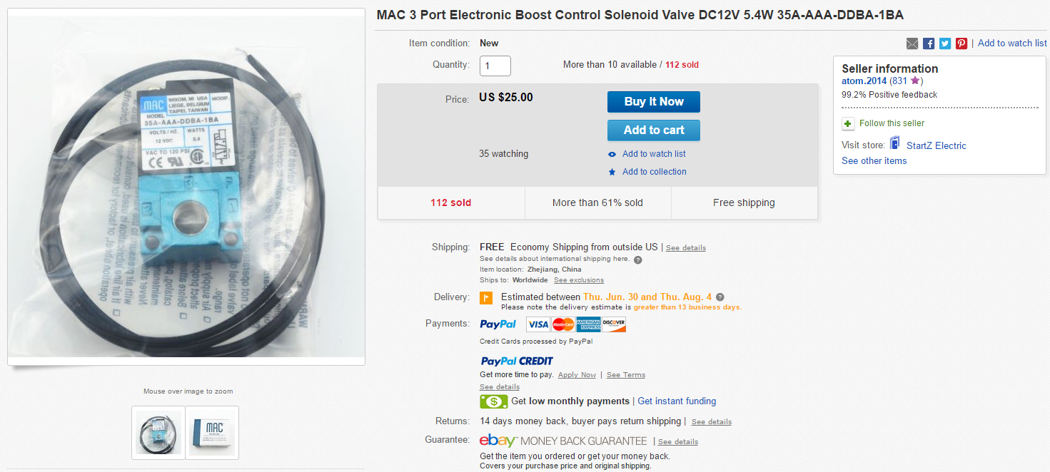
About the EBC itself, you can get a solenoid from ebay for as low as 25$,


PN: 35A-AAA-DDBA-1BA

You should get it with hose barbs.

Connect the EBC between your boost source: the compressor housing or before the throttle (best) and to  your wastgate actuator.

Before throttle ---->MAC Port 1
Mac Port 2      ---->Wastgate actuator

Now after the EBC is connected to the ECU via 3B pin (to ALED) we can test it via TS outputs test mode.

Click on "CAN bus/Testmodes" button (upper left), when you are online with the ECU click "Enable Test Mode", set "Pulse Frequency" to 26Hz and then click on "Pulsed" under ALED, if all is good you should hear the EBC clicking.

Click "Disable Test Mode" and lets go tune this SOB !


Wednesday, June 8, 2016

DIYPNP Firmware upgrade or On the way to EBC...

Hey !

I wanted to install an EBC(Electronic Boost Controller) that I can control from the ECU for a long time now, I noticed that there is "Boost control" circuit on the DIYPNP.


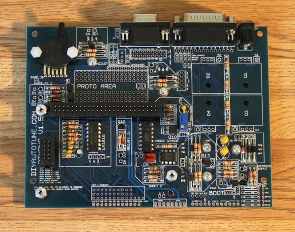
Upper left corner, between the MAP sensor and the DB9 (COM) connector.

The Boost control circuit is needed only when using outputs that can not drive the solenoid directly, PA0,PT6 and PT7.

I had ALED output available that can be used directly to control the solenoid.

OK ? great.. but ! I noticed that I can not select ALED as the EBC output...
Turns out I need to upgrade the firmware. to 3.4.x I was at 3.3.2.

***Using ALED for EBC does not work yet - bug reported, hopefully on 3.4.3 Beta2 and above it will work right.***

Quick workaround was switching between PA0 and ALED outputs, using PA0 for EBC and ALED for fans.

PA0 must go to "Boost Control" circuit.
PA0 -->Boost IN


Boost Out---> EBC pin 

So, first thing to do is to upgrade the firmware, then EBC wiring on the DIYPNP and then TS(Tunerstudio) EBC setup and tune.

DIYPNP firmware upgrade:

***IMPORTENT***

First thing to understand about the firmware upgrade (any firmware upgrade on any device) is that you are about to erase and rewrite the most basic component that makes this thing alive.

If something goes wrong the device is unusable (sometimes there are ways to revive it but most of the time you're F***ed).

Be sure all the connections you made are good, power to the ECU, RS232 cable.
Make sure you use the right firmware, and make sure you choose the right options when you upgrade.

When you upgrade do it slowly, read everything in the upgrade process, and if you are not sure **DO NOT DO IT**

Ok then, lets start.
First thing, download the right FW(firmware):

http://www.msextra.com/downloads/


Make sure your ECU is connected to the PC/Laptop.

Just before you continue, make sure you have a copy of your last good tune (MSQ).

Now run: "ms2loader_win32.exe"


I upgrade the ECU on the table (out of the car) with an external 12V connected to it.
If you try to upgrade when the ECU is in the car, try to follow the instructions/warnings on-screen.

Now, press ENTER.


Press ENTER.


Press ENTER.


Press ENTER.


Press ENTER.


Press ENTER.


For DIYPNP choose "3" and press Enter.


Choose "y" and press Enter

FW upgrade is commencing...

Next thing, fire TS and connect to the upgraded ECU, could be some errors and warnings, you can view them, anyway you should load your last tune and make sure all settings are right and in place.

You can now find ALED under "Boost Control Pin":


***Using ALED for EBC does not work yet - bug reported, hopefully on 3.4.3 Beta2 and above it will work right.***

Great !

Now for the internal wiring...


BTW:
The new upcoming Tunerstudio 3 will have integrated FW update util, this is a screenshot from the beta:


Wednesday, April 13, 2016

TD04 Turbos - Decodeing

Hey,

No tuning today :) just some turbo info.

Today I will write about the well known TD04 turbo family, I hear and see a lot of people refer to a specific turbo from the family as TD04 and that's it...

Well, TD04 range from very small turbos to quite big ones... less then 49mm upto 58mm.

Let me help you out.

Lets take the Volvo 850 T5 stock turbo, it is a TD04HL-15G, lets decode it.

TD04 is the hot side family, HL is the hot side wheel size, 15G is the cold side wheel size - k ?

More -->

CHRA:


Center housing/hub rotating assembly

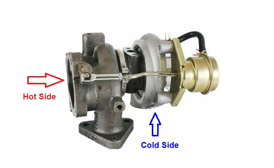
On the left is the hot side wheel and on the right is the cold side wheel.


A = Inducer
B = Exducer


TD04 hot side names and wheels sizes:
TD04      40/47 (A = 40mm, B=47mm)
TD04L    41.3/47
TD04H    44.2/52
TD04HL  45.6/52

TD04 cold side names and wheels sizes:
9B34.8/48.79
11B37.05/49
11G37.97/49
12T37.81/49
13T-438.3/51
13T-640.64/56
13C39.9/52.99
13G41.5/56
13T40.64/56
15T42/56
15G43.37/56.01
16T43.4/56
19T46/58
20T47/58

There are some hot side housing (turbine) designs, some are 2.75",3" or angled, what you need to remember is that all TD04HL will interchange with any other TD04HL turbine design, meaning, the CHRA from one TD04HL will fit another TD04HL even if its design is different.

But you can not cross interchange, TD04H will not fit TD04HL CHRA, you get the point - right ?
The cold side is wheel size limited, so you can not change a 13C CHRA with a 16T CHRA... you will need a bigger 16T cold side (compressor) housing.


Next: TD05...


Thursday, March 31, 2016

REV1.1 Idle spark settings

Hey,

Just a little update on idle spark.

On "Basic Idle Settings" I told you about setting idle cells @ 14-16deg - well don't - if you want your idle to improve set it @ 10deg - like Mazda engineers did...


Idle kpa @ idle rpm will get 10deg.

It will make your idle less sensitive to AFR change and will help it stay stable and nice :)

Tuesday, February 9, 2016

How to test injection order.


I must come clean and tell you all that my injection order was wrong for about a year, since I installed the seq inj module, I got the installation information with a mistake and I have found it just recently.

Someone drooped me a comment about the seq inj order I posted on the seq inj post, he was right, my order was wrong.

Now I will tell you how to test it.

Normal injection order in 4 cylinder engine:

Cylinder 1 is the closest to the timing, cylinder 4 is the furthest.

First to fire: Cylinder 1
Second :      Cylinder 3
Third:          Cylinder 4
Forth:          Cylinder 2

1-3-4-2

In order to test your sequential injection order do the following:

Click on "CAN bus/Testmodes"
Click on "Output TestMode - Inj/Spk"

Here you can see you can test your fuel pump. coils and injectors, we will test the injectors.

Click on "Enable Test Mode" at the top of this window.

Injector Channel To Test: start with 1 and press start, that should make cylinder 1 injector work (you can hear and feel it)

Then:
Inj2, should fire cylinder 3
Inj3, should fire cylinder 4
Inj4, should fire cylinder 2

Click "Stop"
Click on "Disable Test Mode" at the top of this window.

Got it ?

GOOD !


Thursday, December 31, 2015

Closed Loop Idle REV 2.0

Closed Loop Idle REV 2.0

Rev 2.1 of this is post is available - check it out - new and improved !

Overview
CLI is intended to help keep steady idle when load on the engine change, AC, fans, lights etc',
and when high or low CLT and MAT represented to the engine.

CLI control the idle valve which is an air valve that bypass the throttle.
You can help controlling the idle with ignition degree change:
More ignition degree = higher rpm.
Less ignition degree = lower rpm.

On my car it was not needed, but good to know.

After some time you run open-loop (PWM-Warmup) and all is good, meaning the idle valve is operational, you can get a relatively good idle and AFR, it is time to try CLI.

Let's dive in, put your swimsuit on.

Closed Loop Idle 

CLI is dynamic air correction mechanism using PWM-idle air valve.

PWM-idle air valve allow air in the engine when the throttle is closed, when the gas paddle is lifted.

CLI will automatically control the PWM-idle air valve in order to take care of air supply to the engine.

Change "Algorithm" to "Closed-loop"


Main CLI menu:


If you look carefully at the sub menus in this form you can see three sub menus concerning PID and one sub menu concerning CLI valve...

The first sub menu - "Closed Loop Idle Valve setting" has a little misleading name, this settings define the behavior of the valve when releasing the throttle paddle not when CLI is on. 
When in open-loop. 
Eventually leading to idle.

So, in "Closed Loop Idle" settings, you define IAC(idle air control valve) behavior when in open-loop (PID disabled) and for closed-loop (PID enabled).

I know it is a little confusing, but this is how it is...
A part of CLI settings is open loop IAC behavior - on its way to closed-loop.

The other three PID menus define the delay, behavior and activation values for PID operation.
We start at the first sub menu:

Closed Loop Idle Valve setting:
Idle Valve Close Duty(%): Remember "Output Test mode - Idle Valve" ? put the value you've found, here.
(max closed %)
Idle Valve Open Duty(%): same as above (max opened %)
Dahspot Adder(%): The amount of valve % to add when throttle is lifted. (getting ready for idle rpm)
Dahspot Decay Factor(sec?): How long will it take the adder above to decline to 0 - leaving CLI to follow regular CLITR (Closed Loop Idle Target RPM)
Use Last Value Or Table: "Use initial value table" the other option "use last value" did not work good for me.
Use CLT Or MAT In Table Lookup: I use MAT
Close Delay(s): How long will it take the valve to close when throttle is pressed.
Leave Valve Closed Above(rpm): as it says.
For This Number Of Seconds(s): as it says.

Next sub-menu:

Closed-Loop Idle PID Delays And Behavior
PID Delay(s): tool tip
Crank To Run Taper(s): How long to keep following  "Idle Cranking Duty/Steps" curve after engine start
PID Ramp To Target Time(s):  tool tip
PID Control Interval(ms): tool tip
PID Disable RPMdot: tool tip

Closed-Loop Idle PID Activation Settings
Idle Activation TPS Threshold(%): highest TPS that allow PID activation.
RPMdot Thershold(rpm/sec): RPM change speed, how fast the rpm change, close to idle or in idle it will be slow (30rpm/sec is slow)
Max Decel Load(%): Lowest MAP that allow PID activation, should be a little below idle MAP.
PID Lockout On Switch Active: If clutch switch is present you can use it here as CLI activator.
PID RPM Window Size (1=Off): tool tip(?)

Closed Loop Idle PID Gains
tool tips

Settings and settings...., let's talk about the whole CLI concept and what happens when.

When I was tuned to run PWM-Warmup (open-loop idle) I had the IAC (Idle Air Control) set to a specific (low) value for idle.

Goods:
- Easy to set up
- Works (sometimes)

Bads:
- Not dynamic - when load at idle is represented to the system the idle rpm will drop and may even stall, same with low\high CLT and MATit would not "care", it would just do the same (same IAC %) leading to oscillation, too low or too high idle.
- When the throttle is lifted and the clutch is pressed, the rpm run down pretty fast, the static IAC % will not be enough to "hold" and "stop" the rpm from taking a deep dive below desired idle...


CLI - what happen when.
The first trigger that will make MS look into this menu and check what to do is: throttle lift.
When you lift your feet from the throttle, MS is checking to see what IAC % to use in order to give the rpm a "soft" landing just before (=Dashpot Adder) idle (PID idle).

Ok ?

MS will find the answer in "Closed-Loop Idle Initial Values" - meaning, what IAC % @ what MAT/RPM.
I will address this table in a sec.

MS checks the CLT and the looks at CLITR (Closed-Loop Target RPM) to know what IAC % to use.
Next,
So, now the IAC is standing by opened, rpm is decreasing, MS checks for  Closed-Loop Idle PID Activation Settings, TPS is good, RPMdot will be good when the rpm will get close to idle range and Max decel Load will be here when the rpm has "landed" and  the engine is close to normal idle MAP (around 30kpa).

NOW ! PID takes control of the rpm following Closed Loop Idle PID Gains as behavior guidelines.

k ?

1. Throttle lifted
2. IAC % for RPM soft "landing"
3. RPM "landed"
3. PID conditions are met
4. PID controls idle
5. Throttle pressed
6. PID disabled
7. IAC closed

Good ? k !


Closed-Loop Idle Initial Values:
This is the default map values, it is good to start with, I think it will give a little high initial idle but it is great to start with.
After you see/feel that CLI is working, you can tune this little map.


How to tune it ?

Start with 40% in all cells, and keep in mind that low MAT will need less % and high MAT will need more %.

Tune it !

MegaLog Viewer - MLV
If you want to check CLI status in MLV - if MS is in CLI or not, you can choose "status2", when it is 0 CLI is off, when it is 128 CLI is on.


When status2=128 it means that PID is enabled ! 
The whole IAC % landing the rpm is happening before that (every time you lift your feet from the throttle), so you can see in the log that the IAC% is up and status2=0 this is because PID is not active yet, but the IAC % is ready for the rpm...

k ?

Tuner studio
You can add a CLI indicator to TS - just remember it is just the PID activation indicator !


More REV2 to come....

Thursday, September 24, 2015

Mileage, AFR and EGT

Hey,

After some time reading around I have come up with some good info about mileage, AFR and EGT !

Problems:
1. High EGT @ cruise.
2. **Bad** mileage.

Solutions:
1. 40deg~ @ cruise + 15.5:1 AFR (you can go as lean as possible if EGT is good, there is no knock  and no misfire)
2. Lean the map out ! (and read about TPS based AFR table)

The first thing you must understand in the simple truth that if you use less fuel you will have better mileage, simple ah ? turbo likes fuel... we don't like bad mileage, must find good balance...

First thing to do is to tune cruise right, as I stated above, around 40deg~ with lean AFR, you can test how lean you can go just keep in mind, not to high EGT (less then 800C/1500F), no knock and no misfire.

Now cruise is economic as possible.
Tune your idle @ 14.7.

WOT will be 11.5-12.
And the problematic area is the transit area, above 100kpa and below max boost (190kpa in my case).

I use a small turbo (TD04-13C, 40/53mm compressor), every little tip on the gas pedal will get me in to boost (above 100kpa), it can happen starting from a stop light or passing lanes or cars on the highway - when there is no intention to get into boost.

On a "normal" rich AFR map you will see AFR drop from stoich when approaching 100kpa and when passing it it will drop even more - it does not matter how long you "visited" those areas.

We can try and set the AFR table for lean AFR @ 100kpa and above - all before max boost, but it will result a very lean mixture @ 100kpa, if we ever run N/A again it can be a problem. (some times I disconnect my WG in order to run N/A)

Well, a friend of mine told me he runs a TPS based AFR table... very interesting...
AFR will change according to your TPS, high TPS = low AFR, low TPS = high AFR.

It leads to 14.7 in boost sometimes O_O - but for a brief moment while I check my EGT and knock.
He runs this map a few years with great results, I'm starting now - hoping to get good mileage too.

AFR based on TPS as load:


How to enable TPS as load for AFR: