Monday, April 27, 2015

DIY - Use your smartphone as detonation detection tool !

Hey !

Today I will show you how to use your smartphone as a detonation detection tool !

What you need:
- Smartphone with 3.5mm jack utilizing stereo out + microphone.
Like this: (this is a male connector, your smartphone is obviously female, just make sure your original headset jack is the same as in the picture below)

- External Stereo/Microphone adapter
Like this:

- Simple PC Microphone
Like this:

Can be found in any cheap PC microphone and many other devices,

- Alligator style clip
Like this:

- 3m (or any size that fits you) cable for the microphone 

Solder the mic to the cable and place it in the clip
Like this: 


Solder the other end of the cable to a jack
Like this:

Isolated headphone with good noise cancellation 
Like this:


Now your hardware is ready !

You connect the adapter to your smartphone, mic to adapter and headphones to adapter.

Just download an app that keep the mic open (any recording app will do) and you have a DIY  detonation detection tool !

Connect the clip to the engine block, in a typical knock sensor location (for best results)

You can control the volume with the smartphone volume (daaa) :)

P.S You can use a real knock sensor if you want (two wires)
Like this:


:)


Tuesday, March 10, 2015

VE, spark and EGT, I think I got it...

Hey,

I started notice that my EGT while cruising is alarmingly high.

I could get up to 950C/1750F+, at first I thought the EGT is off (it does have a bad ground and the needle jumps around sometimes)

One drive when I was cruising @ 100kph/60mph~ I saw the EGT is very high, for every little gas pedal moment the EGT would raise even more...

It was dark, I pulled over and opened the hood, the exhaust manifold and the turbo turbine were glowing red like I never saw it !

Investigation begins...

Many reading days later, conclusions:

- Higher BTDC degree = Less EGT = Less power
- AFR lower or higher then 14.7 = Less EGT

My ignition map when EGT was too high:


The marked area is my cruise cells.


I added spark to the cruise area like so:


The EGT dropped by as much as 300C/570F~ !!
Of course the power in the area dropped too.

I'm ultra happy with my little win :)

Now I need to find the right balance between EGT and powa.

***UPDATE***

Beside the ignition map update I did something else that I didn't thought is responsible for the big change in EGT - I was wrong...

As I wrote:
- AFR lower or higher then 14.7 = Less EGT, max EGT @ 14.7

I changed my afr map - that is incorporated into ve table, so every change I make in the afr table should bring the afr to the value present.

High EGT AFR Table:


Keep in mind that my wideband could be off a little... still checking.

Low EGT AFR Table:


As  I wrote:
(real) 14.7 will get the highest EGT, lower or higher AFR should get lower EGT, so...

15.4 got me very high EGT, 14.7 gave very cool EGT, I think my wideband is a little off.
Could be my 15.4 is closer to real 14.7 and my 14.7 is lower then real 14.7.

I need to find a way to check that.

Anyway the AFR change made the big difference in EGT.

Change it and you will see the difference in no time.

:)

*****In the new post about mileage EGT and AFR I sort things out - please check it out.*****


Sunday, February 8, 2015

Sequential Injection, installation and setup #2

TunerStudio seq inj setup:


Settings to change:
Squirts Per Engine Cycle: 1
Injector Staging: Simultaneous

Sequential Injection: Sequential/Semi-sequential
Timing Trigger: End-of pulse
Fixed Timing or Table: Fixed Timing
Fixed injection Timing 1(deg): -350
Cranking Injection Timing 1(deg): 360
Injector Drivers: Additional drivers

k?
k!

When I was running batch, I used to hear that the injection timing is not right, but I couldn't do anything about it, now I can !

"Fixed injection Timing 1(deg)" will let you choose the deg you want the injector to shoot, you want it to shoot when the intake valve is closed.

You can play around with numbers, -350=370 if it makes it easier for you.
A full explanation can be found here:
http://www.jbperf.com/sequential/index.html

And here:
http://www.extraefi.co.uk/Seq_MS2.html

Make sure you use the numbers I gave or from DIYAUTOTUNE (which are the same).

Another thing, "Fixed Timing or Table", fixed timing of ~-350 will work, but a table with changing injection deg will work better (less fuel will be used)

This is the table I came up with:


This table works ok, if you want it perfect you need to tune it on a dyno.

Another advanced option, is "VE trim tables", when you enable this you can trim each injector in order to reach the same AFR/EGT on all cylinders...

I think you need 4 widebands/EGT for that.

After I finished installing and tuning seq inj, I've found out:

1. I need less fuel in general on fuel map - lower VE.
2. I don't need AE for now... (!) on the little tune trip I made I disabled AE and noticed car runs great ! (I will keep an eye on this)
3. Smoother idle - more accurate.
4. Better throttle response all around.

Thank you for reading !
Drop a comment !
Be safe !

Next:
Barometric correction for 14$

Sequential Injection, installation and setup #1

Hey,

I just finished installing and setting up my seq inj kit.

Let me show you what is it about.

I'm talking about DIYPNP, other MS ECUs already feature seq inj or they can be upgraded in a similar way - check specific instruction for you specific ECU.

The kit:
Kit


Installation instruction:
Instructions

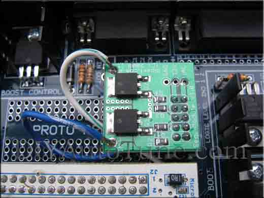
You need to solder the kit male header to the location pointed in the pic:

After Installation:


I run my MS without seq inj for sometime (if  I knew about it the first place I would have installed it from day one...)

Anyway, the default inj installation is batch (running two injectors at the same time), so two injectors were connected to one driver, as follow:


 You can see that INJ1 shoot 4U and 4W and INJ2 shoot 4V and 4X.

The seq inj kit will give us 2 extra INJ drivers (4 total) INJ3,INJ4.
Now !
Which INJ to which  pin ? (4U,4W,4V,4X)
I had to contact support for that - I think it should be a part of the instruction...

The instruction does say :
Main board INJ1: Cylinder 1
Main board INJ2: Cylinder 3
Expansion board INJ3: Cylinder 4
Expansion board INJ4: Cylinder 2

But it does not say nowhere (I looked...) which pin represent which cylinder...

And the answer is (for 96-97 Miata):

Output "INJ1" - 4U - Cylinder 1 Injector
Output "INJ2" - 4W - Cylinder 3 Injector
Output "INJ3" - 4X - Cylinder 4 Injector
Output "INJ4" - 4V - Cylinder 2 Injector

96-97 Diagram - Page 9

My DIYPNP:


The black wire on the left is just passing through the hole on the PCB, on its way to 4V.


Tuesday, January 13, 2015

Sequential Injection Kit

Hey !

Sequential injection means firing each injector separately.
MS default is batch fire, meaning two injector fire at the same time.

Miata (94 and above) run sequential from factory, each injector wire goes all the way to the ECU separately.

So, if your Miata is 94 and above you should start off with sequential injection from the start.
In order to enable sequential injection, you need to add a little module to your MS (DIYPNP only) that will add two additional drivers for the injectors.

The module:

Sequential injection gives you: better efficiency, injection timing, idle smoother, idle smoother with larger injectors, better enrichment, better throttle response.


Do it ! it's good for you !

Monday, December 8, 2014

Spark Map and Tune

Spark Map and Tune

Basically you want to tune spark on a dyno, and give someone that it is not his first time tuning spark to tune it for you...

How to look on a spark map:


Spark can be dangerous  to your engine, if knock knock on your door your engine could go byebye.
Because of that, if you're a beginner at tuning, I suggest you give the spark tuning to someone experienced - on a dyno.

I understand that my high rpm/kpa cells can use less deg, but this is knock free dyno tested (200whp)

Next:
- TPSdot Uses %WOT
- Getting ready for dyno
- MLV - MegaLogViewer
- TS - TunerStudio dashboards