Monday, December 8, 2014

Spark Map and Tune

Spark Map and Tune

Basically you want to tune spark on a dyno, and give someone that it is not his first time tuning spark to tune it for you...

How to look on a spark map:


Spark can be dangerous  to your engine, if knock knock on your door your engine could go byebye.
Because of that, if you're a beginner at tuning, I suggest you give the spark tuning to someone experienced - on a dyno.

I understand that my high rpm/kpa cells can use less deg, but this is knock free dyno tested (200whp)

Next:
- TPSdot Uses %WOT
- Getting ready for dyno
- MLV - MegaLogViewer
- TS - TunerStudio dashboards

Closed Loop Idle Target RPMs & PID tune

Hey !

Closed Loop Idle Target RPMs
Closed Loop Idle Target RPMs is where you setup your CLT to RPM curve.


This is my curve, 1600rpm when cold, down to 900rpm when hot.

Every time you start your engine after you set up this curve, pay attention to the rpm, and adjust the curve to your liking.


Closed Loop Idle PID Gains tune


From: MSEXTRA Manual
  • Proportional Gain This setting controls the Proportional Gain of the PID algorithm. Setting this higher will result in a larger immediate response to changes in RPM. Setting this too high can result in unwanted oscillation of RPM.
  • Integral Gain This setting controls the Integral Gain of the PID algorithm. This is the PID setting used to actually make the RPM meet the target RPM. Setting it too low will cause the RPM to never reach the target. Setting this value too high will result in unwanted oscillation of RPM.
  • Derivative Gain This setting controls the Derivative Gain of the PID algorithm. It can be used to help dampen the effects of the Proportional and Integral settings. It is usually not necessary for good control of Idle speed. It is recommended that this is left at 0%.
PID Tune
  1. Zero all the gains - Set all the gains to 0%. This is so that the effects of tuning the I-term in the next step are not confused with the effects of any other setting.
  2. Tune the Integral (I) gain - The Integral gain is the only term that controls whether the code actually reaches its target. Higher values for Integral gain will result in the code being able to get closer to the commanded target; however, a value that is too high will result in oscillation. The easiest way to determine a good value for the I term is to keep increasing it until oscillation occurs, then slightly lower it. If this value is increased to 200% without reaching a point where oscillation occurs, then the RPM with valve opened setting can be decreased as far as necessary, and the open duty/steps setting and closed duty/steps setting can be made further apart to make the PID loop more sensitive.
  3. Tune the Proportional (P) gain - After tuning the I gain so that the RPM reaches the commanded target without oscillation, the P gain can be tuned. The best way to tune this is to set it as high as possible without getting any oscillation. After setting this, try turning on the air conditioning or other accessories that normally lower RPM or increase load. When these accessories are turned on, the RPM should dip a bit then recover (the valve position should increase significantly). Using longer PID ramp to target times can also make it so that when the PID algorithm engages, a higher P gain can be set without causing oscillation.
  4. Tune the Derivative (D) gain - For most users, use of the D gain should not be necessary. It substantially dampens the response of the loop.


Thursday, December 4, 2014

Closed Loop Idle

Back to idle :)

Rev2 of this is post is available - check it out - new and improved !

Closed Loop Idle - Overview

CLI is a feature that intended to keep the idle steady and consistent regardless of  internal/external physical conditions change. (AFR, MAP, CLT, IAT etc')

In order to control a changing conditions environment you need dynamically changing mechanisms.

Dynamically changing mechanisms is a long and high name for:
- EGO - Dynamic fuel correction
- Idle advance - Dynamic spark correction
- CLI - Dynamic Air correction

When you can control fuel,air and spark - you are the master of your engine.

When you get all three tuned right - your idle will be very close/better to/then factory idle :)

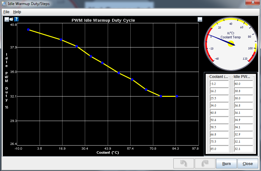
After some time you run open-loop (PWM-Warmup) and all is good, meaning the idle valve is operational, you can get a relatively good idle and AFR, it is time to try CLI.

Let's dive in, put your swimsuit on.
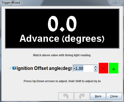
Idle advance

Idle advance is dynamic spark correction.
It will try and help you keep a steady idle even when conditions change.
It does not keep idle by it self, it is responsible of the spark side of idle.


Idle Advance On: Adaptive - in order to prepare the ground for CLI (closed loop idle).
Apply As: Adder - an addition to spark map value.
Condition Is: CL PID - when CLI is active Idle Advance kicks in (if needed)

After you choose "Adaptive" and close the menu, you will have "Idle Adaptive Timing" enabled.
open it...


Can you see what I did there ?

If rpm drops for any reason, it will add timing in order to "help" the engine recover.

Update:

"Braineack" from Miataturbo forum pointed out that the "idle advance" curve should take care of over rpm situations, not only under rpm...

I think it should look something like this:


Added spark when under rpm and under spark when over rpm.

I use the first table (only under rpm correction, works good for me).

Closed Loop Idle 

CLI is dynamic air correction mechanism using PWM-valve.

PWM-valve allow air in the engine when the throttle is closed, gas paddle lifted.

CLI will automatically control PWM-valve in order to take care of air supply to the engine.

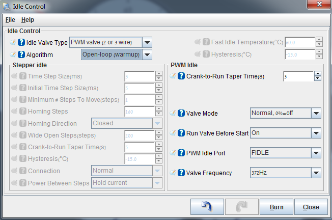
Change "Algorithm" to "Closed-loop"


Main CLI menu:


PID
proportional-integral-derivative controller (PID controller) is a control loop feedback mechanism (controller) widely used in industrial control systems. A PID controller calculates an error value as the difference between a measured process variable and a desired setpoint. The controller attempts to minimize the error by adjusting the process through use of a manipulated variable.

If you look carefully at the sub menus in this form you can see three sub menus concerning PID and one sub menu concerning CLI valve...


The first sub menu - "Closed Loop Idle Valve setting" has a little misleading name, this settings define the behavior of the valve when releasing the throttle paddle. 
When in open-loop. 
Eventually leading to idle.

So, in "Closed Loop Idle" settings you define IAC behavior when in open-loop (PID disabled) and for closed-loop (PID enabled).

I know it is a little confusing, but this is how it is...
A part of CLI settings is open loop IAC behavior - on its way to closed-loop.

The other three PID menus define the delay, behavior and activation values for PID operation.
We start at the first sub menu:

Closed Loop Idle Valve setting:
Idle Valve Close Duty(%): Remember "Output Test mode - Idle Valve" ? put the value you've found, here.
(max closed %)
Idle Valve Open Duty(%): same as above (max opened %)
Dahspot Adder(%): The amount of valve % to add when throttle is lifted. (getting ready for idle rpm)
Dahspot Decay Factor(sec?): How long will it take the adder above to decline to 0 - leaving CLI to follow regular CLITR (Closed Loop Idle Target RPM)
Use Last Value Or Table: "Use initial value table" the other option "use last value" did not work good for me.
Use CLT Or MAT In Table Lookup: I use CLT
Close Delay(s): How long will it take the valve to close when throttle is pressed.
Leave Valve Closed Above(rpm): as it says.
For This Number Of Seconds(s): as it says.

Next sub-menu:

Closed-Loop Idle PID Delays And Behavior
PID Delay(s): tool tip
Crank To Run Taper(s): How long to keep following  "Idle Cranking Duty/Steps" curve after engine start
PID Ramp To Target Time(s):  tool tip
PID Control Interval(ms): tool tip
PID Disable RPMdot: tool tip

Closed-Loop Idle PID Activation Settings
Idle Activation TPS Threshold(%): highest TPS that allow PID activation.
RPMdot Thershold(rpm/sec): RPM change speed, how fast the rpm change, close to idle or in idle it will be slow (30rpm/sec is slow)
Max Decel Load(%): Lowest MAP that allow PID activation, should be a little below idle MAP.
PID Lockout On Switch Active: If clutch switch is present you can use it here as CLI activator.
PID RPM Window Size (1=Off): tool tip(?)

Closed Loop Idle PID Gains
tool tips

Settings and settings...., let's talk about the whole CLI concept and what happens when.

When I was tuned to run PWM-Warmup (open-loop idle) I had the IAC (Idle Air Control) set to a specific (low) value for idle.

Goods:
- Easy to set up
- Works (sometimes)

Bads:
- Not dynamic - when the physical conditions for the engine change, it would not "care", it would just do the same (same IAC %) leading to oscillation, too low or too high idle.
- When the throttle is lifted and the clutch is pressed, the rpm run down pretty fast, the static IAC % will not be enough to "hold" and "stop" the rpm from taking a deep dive below desired idle...
When A/C is on, it is even worse, it can even lead to engine stall.

SO !

In order to make idle "smart" and sexy like factory idle, we must enable some auto correction features.

CLI - what happen when.
The first trigger that will make MS look into this menu and check what to do is: throttle lift.
When you lift your leg from the throttle MS is checking to see what IAC % to use in order to give the rpm a "soft" landing just before (=Dashpot Adder) idle (PID idle).

Ok ?

MS will find the answer in "Closed-Loop Idle Initial Values" - meaning, what IAC % @ what CLT/RPM.
I will address this table in a sec.

MS checks the CLT and the looks at CLITR (Closed-Loop Target RPM) to know what IAC % to use.
Next,
So, now the IAC is standing by opened, rpm is decreasing, MS checks for  Closed-Loop Idle PID Activation Settings, TPS is good, RPMdot will be good when the rpm will get close to idle range and Max decel Load will be here when the rpm has "landed" and  the engine is close to normal idle MAP (around 30kpa).

NOW ! PID takes control of the rpm following Closed Loop Idle PID Gains as behavior guidelines.

k ?

1. Throttle lifted
2. IAC % for RPM soft "landing"
3. RPM "landed"
3. PID conditions are met
4. PID controls idle
5. Throttle pressed
6. PID disabled
7. IAC closed

Good ? k !

Don't forget that all this is just the automatic air control for idle, automated fuel (EGO) and spark (idle advance) must be right on too.

Closed-Loop Idle Initial Values:
This is the default map values, it is good to start with, I think it will give a little high initial idle but it is great to start with.
After you see/feel that CLI is working, you can tune this little map.


How to tune it ? LOG !

You log a normal drive you take and check it out, you can find in the log what IAC % give what RPM (roughly)  put those numbers in this table, don't forget that @ low CLT the idle will need more IAC % then when high CLT (operation temperature).

This is my table:


MegaLog Viewer - MLV
If you want to check CLI status in MLV - if MS is in CLI or not, you can choose "status2", when it is 0 CLI is off, when it is 128 CLI is on.


When status2=128 it means that PID is enabled ! 
The whole IAC % landing the rpm is happening before that (every time you lift your foot from the throttle), so you can see in the log that the IAC% is up and status2=0 this is because PID is not active yet, but the IAC % is ready for the rpm...

k ?

Tuner studio
You can add a CLI indicator to TS - just remember it is just the PID activation indicator !


Next:
- Closed Loop Idle Target RPMs
- Closed Loop Idle PID Gains tune
- Spark map
- EGO in boost (?)
- Getting ready for dyno

Wednesday, December 3, 2014

A/C Idle Up

Hey ! let's roll...


A/C Idle Up


Very nice and helpful feature, that will rise the rpm just before engaging the A/C compressor in order to avoid the annoying rpm drop when A/C kicks in.

I use a DIYPNP version of MS.
My A/C is wired like that:
1K > Input1 IN > Input1 OUT > PE1

WLED > 1B&1G

Idle-up Duty Adder(%): How much PWM Idle valve % to add before A/C switched on.
Idle-up Target RPM adder(rpm): How much rpm to add to CLI Target Curve.


WLED is disabled here, it is only configured in the A/C Idle up menu as Idle-Up Output.

Next:
Closed Loop Idle
Idle Advance 


Monday, December 1, 2014

Over Boost protection and Rev Limier

Today: Protection.

Over Boost and Rev Limiter.

Over Boost Protection

Over Boost will save you from dangerously unwanted boost level.


Under boost control settings you can set the Overboost Protection.
You can choose between Spark or fuel cut, or both.
Then you set the max boost - in kpa - 200kpa = 14.5psi = 1bar of boost.
Hysteresis is the kpa level below max boost where spark/fuel are re-enabled.

Set it right, it's important, especially when playing with boost controllers, actuators springs or other boost altering devices.


Rev Limiter

We all know what a rev limiter is, but here you can set a "smart" rev limiter.
I use "CLT based" rev limiter in order to limit rev on high\low CLT.


Lets go through the options:

HARD REV LIMIT:
Hard rev limit(RPM): RPM limit - 7200rpm for a stock internals miata - same as stock ECU.
Soft Limit Zone / Hysteresis(RPM): RPM needs to drop by this much from max RPM before fuel is re-enabled.

COOLANT TEMP LIMITER
Rev Limiter CLT Based: You can choose between normal rev limiter - only max rpm, or you can choose CLT based, that will let you use rev limiter in a more creative way.
Rev Limit TPS Bypass(TPS %): At what TPS % the rev limiter settings are ignored.
I recommend setting it close to 100% in order to allow emergency WOT.
RPM When In TPS Bypass(RPM): The new rev limiter when in bypass TPS %.
I think 7200rpm is good here also.

For all the rest of the options, no extra info - read the tool tip.


More to come:
- High resolution AFR table.
- Idle advance
- A/C idle up
- Closed loop idle
- Spark map
- Required Fuel
- Getting ready for dyno

Sunday, November 30, 2014

Acceleration Enrichment and Over-Run Fuel Cut

Back !

The next things to take care of under fuel tuning is Acceleration Enrichment and Over-Run Fuel Cut, stay tuned... :)


Acceleration Enrichment - AE:

What is AE and why do we need it - and what is EAE... ?
AE is a function that takes care of fuel when you go from TPS 0% to TPS >0%.
Why is it needed ?
When the throttle is unpressed (TPS=0%~)  and you press the throttle (TPS>0%~) you open the throttle body and let air in the manifold, the engine goes something like, "mmm OK, air is good but what about fuel.... mixxturree tooo leeeaaannnnn I CAN NOT RUN ! HELP !

Same happens when you start moving, shifting gears or just rev it.

What we want to do is, let MS know how much fuel to add (Pulsewidth added ms) when rapid change in TPS is sensed.

Picture:


You can just try the settings in the pic.

Lets go over a few options:
- Accel Enrichment MAPdot<-->TPSdot Blend(%)
You choose if you want AE to work with MAP or TPS as guideline.
If your TPS is good and not too noisy - choose 100% TPS

- Accel TPSdot Threshold (%/s): 
TPSdot = TPS + "dot" part is "derivative over time", speed of change.
The threshold is the point you want AE to kick in.

You can start with the second way I used to tune AE. (Scroll down a little)

You want to log the situations where your TPSdot makes you lean & impact drive-ability.
Static rev, gear shifting etc'.

In the log you will see what TPSdot level makes you lean.
These are the points you want to fix and let AE make them less lean - more rich.

You can see in my log:
TPS (green) going from 0% to 90% fast - around 200 %/sec TPSdot,
TPSdot - white
AFR (red) going lean 20:1- the spike
Pulsewidth Added ms (yellow) - because of the lean AFR you can understand that "added ms" is too low.


Tune the AE until it is not too lean or too rich, numbers aside, drive-ability is your first priority.
Even if the numbers are not perfect (never will be) and car's running smooth - stop right there !

EAE is Enhanced Acceleration Enrichment, it goes dipper into fuel AE management and is targeting low speed throttle movements with high resolution AE.

Haven't touched it yet, AE works good for me, but maybe some day....

Updated way to tune AE:

1. Zero out all AE "Added ms".
2. Set four TPSdot points. (slow tip, medium, faster and fastest)
3. Set a good TS dashboard to work with...
4. Start with idle rev, try to test the first TPSdot you set until you see the AFR not spiking (no 20:1, more like 14-16:1, no less)
5. move to the next TPSdot and repeat 4.


Set AFR as a "Line graph" under "Gauge style".
Helped me alot !

Turn off Over-Run Fuel Cut, when tuning AE !

Over-Run Fuel Cut
After I got AE tuned so good with Over-Run turned off, I need to look deeper into it before i turn it on again...

Wanna get better mileage ? good. Turn it on then,

Over-Run Fuel Cut: will shut off the fuel to the engine. tune it right and forget about it.

You can try my settings:


More to come...

Thursday, November 27, 2014

Fuel Tuning and Settings

On the menu today:

  • WUE - Warm Up Enrichment
  • AFR Table 
  • Incorporating AFR in to VE table
  • VE Table
  • EGO - Exhaust Gas Oxygen
  • AE - Acceleration Enrichment 
  • Over-Run Fuel Cut


WUE - Warm Up Enrichment

Warm up enrichment, is there to help a cold engine run smooth up to operating temperature.


Normally when warm (85C-90C) the enrichment will be 0, meaning 100% of VE table.
Registered TS (TunerStudio) can auto tune WUE, works great.
If you tune it yourself you want to increase VE % just above the point where the engine is straggling when warming up, try to keep it around 14.7 or a little richer.

Before we start tuning the fuel, I want to explain my strategy.
1. Setup AFR table
2. Enable a cool feature that will make VE tuning very simple.
3. Tune VE table to reach the AFR targets we set in AFR table.


AFR Table:
Is the table that holds your "wish list", where you just put in what AFR you would like to see in each area of the engine operation range (idle, cruise, boost, deceleration etc')

Guidelines:
For idle I found that an AFR of 13.5 is great for me. (Probably because of batch fuel injection, I believe when I will upgrade to sequential injection idle AFR will be 14.7:1)
Cruise 15-16
Deceleration 15-16
Boost 11.5-12

This is my AFR table, it's aggressively lean.


Cool feature:


What we just did is telling the MS to use the value from the AFR table when calculating fuel to squirt.
Meaning, after finishing the first VE tune to match the AFR table we will not need to touch the VE table again (no need to tune the VE any more...)
Any change we want to make to our fuel map we will make through the AFR table.

Example:
Your cruise AFR is 16 and it is too lean(misfire), all you have to do in order to change it, is just to change the AFR cells you want in the AFR table.

Because the AFR target value is incorporated in the fuel calculation, the VE outcome (squirt) will change accordingly.  

Got it ? good.

VE Table:

This is how you look at a VE/AFR table:
This table is for naturally aspirated engine - idle, cruise and deceleration are the same for forced induction.

The 95-100 kpa range you can set up leaner and 100-200 kpa you scale from 13 to 11.5.


In the picture you can see that cruise cells are 1100-2000 rpm and 45-75kpa, could be your car cruises in a different rpm/kpa range - log it, check it, and AFR it accordingly. 

After you got your AFR table right you can auto tune or manual tune till the VE table reach the  AFR target table.

Now we have a nice AFR table, tuned VE table and an easy way to tune without tuning ;)

Next we need to look at EGO - Exhaust Gas Oxygen.
This nice little mechanism will help us keep our AFR right even at different CLT and IAT.


Works great !

Important pointers:
Controller Auth: is the max VE % you allow the MS to change.


Next: AE - Acceleration Enrichment and Over-Run Fuel Cut


Wednesday, November 26, 2014

Basic idle settings

In order to start tuning we need to stabilize the idle, this is just basic settings in order to get us going.

Overview:

Engine off:
1. Idle ignition
2. Idle fuel/AFR
3. Idle control setup
Engine on:
4. Idle valve test
Engine off:
5. Idle Cranking Duty
6. Idle Warmup Duty

Let's go...

Engine off:

Open your "Ignition Table 1 (Spark Advance)", your normal idle should be around 30kpa (no ac, no lights, no stereo etc...)

Set the idle cells at 14-16 - Read Rev1.1


Open your "Fuel VE Table 1" and set your idle cells with the same number (57 is good for me, your number maybe different to begin with)


Idle control basic settings:

Open "Startup/Idle" ---> "Idle Control"

Set it up like in the picture below:


Engine on:

"Batch Injection" cars will need to run idle a little rich even <14:1.
"Sequential Injection" can run 14.7:1.

Now start your engine and let it fully warm up, now check your AFR gauge, try to get the AFR that is right for your injection method and your engine.
If you are too lean use higher number in the fuel idle cells.
If you are too rich use lower number in the fuel idle cells.

When the idle is right (AFR) the engine will tell you, listen to it.

Now we need to test the idle valve range (gives air to the engine when throttle is closed)

Open "CAN bus/Testmodes" ---> "Output Test mode - Idle Valve"


Start the test at 0% and increase the % until rpm start raising - write the % you have found down.
Continue increasing the % until rpm will not raise any more - write the % you have found down.

Stop the test.

Engine off  !


In my car I found:
0% valve = 26
100% valve = 65

So my valve 0-100% range is 26-65, 26 is closed and 65 is fully open,

Now you can set up your "Idle Cranking Duty/Steps", how high you want the rpm in the first few seconds after engine started.
Usually you would want high when cold low when warn, but both of them should set the rpm around 1500rpm.


Every time you start your engine after you set up this curve, pay attention to the rpm, and adjust the curve to your liking.


Now we'll  setup the "Idle Warmup Duty/Steps" table.
Open "Startup/Idle" --->  "Idle Warmup Duty/Steps"


Here we set up how much valve (air,rpm) we want to add at a specific CLT temp, when cold we need more valve when hot we need less valve.

Every time you start your engine after you set up this curve, pay attention to the rpm, and adjust the curve to your liking.

Not too difficult, after we will finish tuning all the basics and the car will be running ok for some time we will take a shoot at Close Loop Idle (automated idle mechanism) .


Base timing

Base timing tune:

Base timing tune is needed in order for the ignition map to have/use real ignition degree values.
In order for your degree timing numbers to represent a real world outcome.

 10 degree in ignition map = 10 degree in real world.

In order to align that, we need to use a timing light gun

Tooluxe Xenon Automotive Timing Light - Cheap and works
That's what I got.

Now get your timing right !

"Ignition Settings" ---> "Ignition Options / Wheel Decoder" ---> "Fixed Advanced" ---> "Fixed timing"


"Ignition Settings" ---> "Trigger Wizard"


You must know/find your crank pulley marks for TDC and 10 BTDC


Get the marks aligned like in the picture above.

Check the timing at higher rpm upto 6-7K, if the marks move then align them at higher rpm - it is more important then lower rpm alignment.

After you finish, remember to change "Fixed timing" back to "Use table"

"Ignition Settings" ---> "Ignition Options / Wheel Decoder" ---> "Fixed Advanced" ---> "Use table"


Sensors and out puts calibration

Let's start with the basic check list:

1. Install the MS(Meagsquirt) in the car.
2. Install TS(TunerStudio) on a laptop and check connectivity to the MS.
3. Start a new project and set it up.
4. Configure "Required Fuel"
5. Verify all the sensors communicate with TS.
6. Load base maps for your car/engine.
7. Car starts ? good ! turn it off, does not start ? check 1-4.
8. Base timing light gun test.

Tuning order:

Required Fuel:

Setting up "Required Fuel" right will make an injectors change easy and simple.
If you do not set it up you will have to tune again...


Nothing much here, just type in your engine displacement, number of cylinders, injector flow and stoich  AFR for your engine (gasoline is 14.7:1)

Set it up right on your first steps will make injectors change (to smaller/bigger) EASY.

Do it !


Engine off:
First thing to do is calibrate your sensors.


Calibrate TPS - Throttle position
Calibrate Thermistor Tables --> IAT - Intake air temperature (GM open element IAT sensor)


Calibrate Thermistor Tables --> CLT - Coolant temprature (Original Mazda CLT sensor)


Calibrate AFR Table - Air fuel ratio sensor - Wideband - If connected to MS.

Are we good ? ok.

Next we need to setup our "Programmable on/off outputs", in my case I had only the radiator fan behavior to setup.


Check "Enable" to make the settings operational
Set "Power On Value" to "Off" - default behavior of the fan is off.
Set "Active value" to "On" - when triggered we want the fan to start.
Set "Output Channel" to "coolant" 
Set ">" - meaning only when the coolant is > (higher then...)
Set "Threshold" to the temp you would like the fan to start at (90C-95C I think is normal)
Set "Hysteresis" to how much coolant temp should drop below threshold before fan off.


Hey !

This is my new blog, it will be about my Mazda MX5 Miata and the Megasquirt I installed.

Tuning stuff that I learned through my feet.

Let's start and see what happen :)